


Steel Adjustable Shoring
Steel Adjustable Shoring / Vertical Prop
Prefabricated Building Temporary Vertical Support Equipment Product Brochure
1. Product Introduction
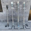
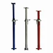
The Steel Adjustable Shoring (Vertical Prop / Shoring Tower) is a core load‑bearing device for the on‑site installation and temporary support of precast concrete components in prefabricated building construction. Manufactured from high‑strength structural steel (Q235B / Q345B / Q390B), it consists of an outer sleeve tube, an inner telescopic core tube, a threaded adjusting collar (or pin‑hole adjustment mechanism), upper/lower support saddles (top plate / base plate), and a locking handle. It is produced via CNC cutting, precision welding, thread machining, stress relief, and surface treatment.
Its core function is to provide controllable, adjustable, and reusable vertical temporary support reaction during the on‑site hoisting and positioning of precast elements (composite slabs, composite beams, precast stairs, balcony slabs, bay windows, wall panels, etc.), sustaining the self‑weight of the component and construction live loads, and ensuring positional accuracy and structural safety before grouting/joint connection / post‑poured concrete reaches design strength. By rotating the adjusting collar or changing the pin hole, stepless / stepped height adjustment of 200–1500 mm (or even wider) is achieved, adapting to different story heights and bottom elevations.
2. Product Parameters & Specifications
| Parameter Category | Typical Specification / Range | Description |
|---|---|---|
| Product Name | Steel Adjustable Shoring / Vertical Prop / Shoring Post | Adjustable steel vertical support |
| Applicable Component | Composite slabs/beams, precast stairs, balconies, bay windows, wall panels | Temporary vertical support for precast elements |
| Material | Q235B / Q345B / Q390B / 16MnDR (low‑temperature) | Per load & site condition |
| Outer Sleeve Tube | Φ48×3.5 / Φ60×4.0 / Φ76×5.0 mm (ERW / seamless) | Per bearing‑capacity calculation |
| Inner Core Tube | Φ41×3.0 / Φ54×3.5 / Φ68×4.0 mm | Matched with outer sleeve |
| Adjustment Mode | Threaded collar (stepless) / Pin‑hole (step, 50 mm module) | Combinational optional |
| Adjustment Travel | 300 / 500 / 800 / 1000 / 1500 mm (customizable) | Per story height & working condition |
| Load Capacity | 10–50 kN per prop | FEA + Euler buckling check, subject to tube diameter/material/height |
| Working Height | 1.0 m – 4.5 m (shorter/longer customizable) | Lateral bracing required if extra‑high |
| Top & Base Saddle | 150×150×10 / 200×200×12 mm steel plate + stiffeners | Customizable to component contact face |
| Surface Treatment | Sa2.5 blasting + zinc‑rich epoxy primer + topcoat / HDG | Corrosion protection per environment |
| Locking Mechanism | Cast‑steel nut + handle / spring pin + safety circlip | Anti‑loosening design |
| Self Weight | 8–45 kg/prop | Varies by specification |
| Safety Standard | GB 51210 / JGJ 300 Temporary Shoring; referencing EN 1065 | 100% factory inspection before shipment |
3. Product Usage Instructions
- Pre‑installation Inspection: Verify the prop model, rated capacity (WLL) against the weight/quantity of the component to be supported; inspect each prop for no bending, no weld cracks, intact threads/pin holes, and reliable locking mechanism. Clean the component bearing face and floor/ground; ensure the top/base saddle contact surfaces are flat and debris‑free; floor bearing capacity must be confirmed by a structural engineer.
- Height Adjustment & Positioning: Place the prop below the designed support point; rotate the threaded collar (or change the pin hole) to adjust to design height so the top saddle contacts the component bottom uniformly and tightly. For multi‑prop combined support, all props shall have uniform height (deviation ≤5 mm) and even load distribution; wooden blocks/stones for heightening are strictly prohibited.
- Locking & Reinforcement: After adjustment, tighten the lock nut/handle or insert the safety pin and confirm the circlip is seated to prevent loosening/retraction in service. When height ≥3 m or subject to horizontal force (wind/hoisting impact), add horizontal ties, cross braces, or lateral stabilization frames to prevent buckling/overturning.
- Coordination with Lifting/Setting: Lower the precast component by crane/equalizing spreader beam to approx. 200–300 mm above the design position, then set it slowly onto the props; release the lifting gear only after confirming 3+ reliable contact points. Assign a dedicated signalman during setting; personnel are strictly prohibited from entering beneath the component or the prop load zone.
- Removal & Turnover: Props may be removed only after joint grouting/post‑poured concrete reaches design strength and the component is self‑supporting; removal sequence: loosen lock → lower height → withdraw. Violent hammering on the tube is prohibited; after withdrawal, clean threads/pin holes, apply anti‑rust oil, stack by category (≤1.5 m high), and re‑inspect before reuse.
4. Application Scenarios
- Composite Slab Support: Temporary vertical support while composite slab is set between beam/wall supports; prevents slab‑end overhang, controls deflection and cracking.
- Composite / Precast Beam Support: Multi‑point temporary support under long‑span composite or precast frame beams; shares self‑weight, ensures stability before joint grouting.
- Precast Stair Support: Temporary support at stair‑flight bottom after hoisting & positioning; prevents overturning, facilitates joint adjustment work.
- Balcony / Bay‑window / AC‑slab Support: Bottom/side auxiliary support for cantilevered components during installation; controls elevation and levelness, anti‑falling protection.
- Wall Panel Vertical Installation Support: Bottom curb + lateral brace combination for vertical wall‑panel erection; ensures verticality & wind‑load stability.
- On‑site Staging Yard: Layered blocking support when precast elements are temporarily stored on site; uniform load transfer, prevents component cracking.
- Municipal / Rail Precast Installation: Temporary support for corridor wall panels, track slabs, bridge barriers; adapts to irregular shapes & complex site conditions.
5. Safety Precautions
5.1 Load & Stability Safety
- Overloading is strictly prohibited; working load per prop shall not exceed rated capacity. For multi‑prop combined support, perform load verification according to actual load distribution; safety factor ≥2.0 for static load and ≥1.5 for dynamic load.
- Verify slenderness ratio λ and buckling capacity per Euler's formula; lateral braces or cross bracing shall be mandatory when working‑height/tube‑diameter ratio is excessive.
5.2 Foundation & Wind Safety
- Floor or ground bearing capacity must be confirmed by engineer; spread steel plates on soft ground to distribute pressure and prevent settlement or overturning.
- Stop hoisting & shoring work at Beaufort 6 (≥10.8 m/s) and above; anchor or add ballast for outdoor‑stored props against tipping hazard.
5.3 Operation & Lifting Safety
- Confirm lock nut or safety pin is fully seated before every use; immediately withdraw from service if thread slipping or pin‑hole ovalization is detected.
- Personnel are prohibited from staying underneath components during lowering; certified signalman shall take charge of hoisting command; keep safe clearance between crane and shoring system.
- For installation or removal work above 2 m height, erect scaffolding or working platform and wear safety harness; never throw tools up and down.
5.4 Inspection & Storage Safety
- Carry out comprehensive inspection every 12 months or every 200 service cycles: UT/MT sampling inspection for welds, tube straightness measurement, thread and pin‑hole wear check.
- Store in dry well‑drained area, pad with wooden blocks ≥150 mm high. Stack flat height ≤1.5 m or store upright; keep away from fire sources and corrosive media.
6. OEM & ODM Customization Services
We provide comprehensive customization services to meet global clients' diverse needs:
- Size Customization: Per component self‑weight, support‑point quantity, story height & bottom elevation — customize outer/inner tube diameter, wall thickness, adjustment travel (300–1500 mm or longer) & working height (1.0–4.5 m or per request).
- Material Upgrade: Optional Q345B, Q390B, 16MnDR (low‑temp), high‑strength seamless tube for heavy‑duty, cold or corrosive working conditions.
- Adjustment Mechanism: Threaded stepless (precision cast‑steel nut), pin‑hole step (50 mm module), or combined structure; quick‑release handle is available option.
- Saddle Customization: Top saddle in flat plate, U‑cradle, V‑cradle, rubber pad; base can be fitted with adjustable foot or ball hinge base for sloped roofs and inclined surfaces.
- Surface Treatment: Epoxy coating, HDG hot‑dip galvanizing, powder coating (RAL color), Dacromet for indoor, coastal and chemical‑zone anti‑corrosion requirements.
- Functional Integration: Load‑cell interface, height scale, anti‑settlement alarm device, quick‑connect flange for multi‑prop shoring tower assembly.
- Branding & Packaging: Laser‑engraved client logo, rated capacity, serial number & safety warnings. Export‑grade anti‑rust packaging; support CKD knocked‑down shipment and on‑site assembly.
7. Why Choose Us?
- Industry Expertise: 10+ years R&D and manufacturing of steel support/lifting equipment, serving 20+ countries, over 50 000 props delivered including new and refurbished units.
- Design Capability: In‑house structural engineers; load capacity & Euler buckling verification per GB 51210/JGJ 300 with reference to EN 1065; calculation sheet can be provided upon request.
- Precision Manufacturing: In‑house CNC machining center + auto‑welding + dedicated thread‑machining machines; tube straightness ≤L/1000, thread accuracy 6H/6g.
- Quality Assurance: ISO 9001 certified; every prop undergoes sampling load test + thread/pin‑hole inspection + coating adhesion test before shipment.
- Global Service: 7×24‑hour technical support, 48‑hour after‑sales response. Services contain on‑site installation guidance, support scheme optimization, inspection and refurbishment.
- Cost Advantage: Factory‑direct supply without intermediaries; rent‑or‑sale options plus trade‑in refurbishment, matching diverse budgets and project cycles.