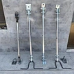
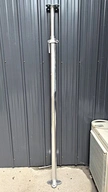
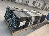
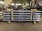
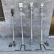
Steel Diagonal Brace
Steel Diagonal Brace / Raking Shoring Prop
Prefabricated Building Temporary Diagonal Bracing Equipment Product Brochure
1. Product Introduction
The Steel Diagonal Brace (also called Raking Shoring Prop) is the core temporary bracing equipment used during on‑site installation of precast concrete components. Manufactured from high‑strength structural steel (Q235B / Q345B / Q390B) via CNC cutting, precision welding, stress relief, machining, and surface treatment, it consists of a length‑adjustable tubular body, upper and lower hinged brackets (with U‑head / ball hinge / connection base plate), a telescopic adjustment mechanism (internal threaded collar + adjustment screw, or pin‑type adjustment), and a locking device.
Its main function is, after a vertical or steeply inclined element such as a precast exterior wall panel, shear wall panel, precast column, or bay‑window wall panel is hoisted into position, to act as a temporary diagonal support — resisting the overturning moment from the component’s self‑weight and horizontal actions such as wind load and construction live load, and holding the component stably at its designed installation position until a permanent and reliable connection is formed with the main structure (cast‑in‑place joints, grouted sleeves, connection bolts, etc.). The product is dimensioned per the supported component’s structural form, geometry, self‑weight, installation height, wind load, and construction conditions; support length, adjustment range, tube wall thickness, and bracket type are determined by structural calculation, then cut, welded, and formed accordingly.
2. Product Parameters & Specifications
| Parameter | Typical Specification / Range | Description |
|---|---|---|
| Product Type | Adjustable / Fixed / Telescopic‑Hinged Diagonal Brace | Per adjustment & bracket type |
| Applicable Element | Exterior wall panel / Shear wall / Precast column / Bay‑window wall | Vertical & steep‑inclined PC parts |
| Tube Material | Q235B / Q345B / Q390B seamless/welded steel tube | Std. / heavy‑duty optional |
| Tube OD × Wall | Φ60×4 ~ Φ168×10 mm (per load calculation) | By slenderness λ & stability check |
| Adjustable Range | 0.8 m – 6.0 m (longer customizable) | Thread adj. or pin‑step adj. |
| Travel / Precision | Thread: continuous, ±5 mm; Pin‑type: step 50/100 mm | Per installation accuracy requirement |
| Rated Working Load Limit (WLL) | 10 kN – 80 kN / unit (higher on request) | FEA + Euler buckling check |
| Safety Factor | Static ≥2.0 / Dynamic ≥1.5 (per code) | GB 51210 / JGJ 300 / EN 1065 |
| Upper/Lower Bracket | U‑head / Ball‑hinge / Drilled connection base plate | Match embedment on element |
| Locking Device | Adjusting nut + lock nut / Pin + safety circlip | Anti‑rotation & anti‑loosening |
| Surface Treatment | HDG (≥65μm) / Zn‑rich epoxy primer + topcoat | Per corrosion environment |
| Hinge Rotation | ±15° ~ ±30° (per ball hinge / pivot pin design) | Tolerates erection angle deviation |
| Self Weight | 15 kg – 120 kg (per length & tube size) | — |
3. Product Usage Instructions
- Pre‑installation Inspection: Verify the brace model, adjustment range, and rated WLL suit the supported component’s conditions. Check the tube for bending, deformation, or cracks; welds for cracking; threads/pin holes for stripping or wear; hinge articulation for smooth and reliable movement; locking nuts and anti‑loosening devices shall be complete and effective.
- Angle Setting & Length Adjustment: Based on erection angle (the angle between brace and horizontal should preferably be ≥30°, ~45° for optimal force transmission) and distance between upper‑lower connection points, calculate required support length. Rotate adjustment nut or select proper pin hole, set brace to design length, tighten lock nut or insert safety pin.
- Bracket Connection & Positioning: Securely connect upper bracket (U‑head/ball hinge) to embedded plate or lifting point of component with bolt/pin plus split pin; fix lower bracket to floor embedment or dedicated ground anchor. Ensure hinges rotate freely, connection pins are safety‑secured, and brace axis passes near component gravity center for effective anti‑overturning moment.
- Cooperation with Erection Lifting: Make preliminary connection for upper and lower brackets before loaded condition. Tension and lock the brace only after component is set and verticality corrected. Releasing crane hook before brace connection and locking is strictly prohibited.
- In‑service Inspection: Periodically check brace tightness, bracket slipping and tube deformation during concrete pouring, grouting and curing. Stop construction and reinforce or remove affected braces when Beaufort 6 wind or above (≥10.8 m/s) occurs.
- Removal & Reuse: Remove braces only after permanent structural connection finished and joint strength meets design requirement (normally ≥75% design strength). Operate by qualified personnel following sequence: loosen lock → remove lower bracket → remove upper bracket. Clean components and apply anti‑rust oil for turnover application.
4. Application Scenarios
- Precast Ext. Wall Panel Erection: Temporary diagonal bracing for façade panels of high‑rise residential & commercial precast buildings, resisting wind force and overturning risk.
- Precast Shear Wall Erection: Temporary fixing for PC shear‑wall components before forming integral performance with cast‑in‑place joints.
- Precast Column Erection: Temporary stabilization support for precast columns of single‑/multi‑story factory and frame structures.
- Bay‑Window Wall Erection: Precise positioning and temporary fixing for irregular wall panels with window openings after hoisting.
- Stair / Balcony Slab Erection: Auxiliary anti‑overturning bracing for long‑span and cantilever precast elements.
- Municipal & Rail Transit Elements: Temporary support for precast piers, noise barriers, tunnel side‑walls and other vertical components.
- Overseas PC & Modular Projects: Standardized diagonal brace configuration for export precast factories and modular building construction sites.
5. Safety Precautions
5.1 Load & Angle Safety
- Working load of single brace shall never exceed rated WLL; verify slenderness ratio λ and buckling‑resistance capacity via Euler stability calculation.
- The included angle between brace and horizontal plane should preferably be ≥30°, avoid sharp small angle which will cause sharp increase of axial force.
5.2 Connection & Lifting Safety
- All upper/lower bracket bolts and pins must be equipped with complete anti‑loosening accessories including lock nut, split pin and circlip; virtual connection or missing fittings is forbidden.
- Crane hook shall not be released before brace locking; perform tension operation only after component positioning and verticality calibration completed.
5.3 On‑site Operation Safety
- Suspend relevant work under Beaufort 6 wind (≥10.8 m/s) or above; reinforce or dismantle affected diagonal braces.
- Regularly inspect tube bending/deformation, weld crack and bracket abrasion; take product out‑of‑service once over‑tolerance phenomenon appears.
- Unified command and synchronized actions required during installation and dismantling, prevent crush injury and overturning hazard.
- Wear safety harness and set safety net for working‑at‑height; personnel access is permitted only after component temporary fixation finished.
5.4 Storage Safety
- Store in dry location supported by wooden sleepers; fix tubes laid flat or erected to avoid rolling and rust corrosion.
6. OEM & ODM Customization Services
We provide comprehensive customization services to meet global clients’ diverse needs:
- Size Customization: Custom support length (0.8‑6 m or longer) and telescopic travel according to component erection height, bracing angle and adjustment requirements.
- Material Upgrade: Optional Q345B, Q390B, 16MnDR for low‑temperature environment and high‑strength seamless steel tube for high‑load‑low‑self‑weight condition.
- Adjustment Mechanism: Threaded continuous high‑precision adjustment, pin‑step fast‑erection adjustment, hydraulic jacking heavy‑duty automatic adjustment for selection.
- Bracket Type Customization: U‑head, ball‑hinge base, drilled connection plate and magnetic base, matching different embedded parts and component forms.
- Surface Treatment: HDG hot‑dip galvanizing, epoxy coating, RAL‑color powder coating, Dacromet to satisfy various anti‑corrosion environment.
- Function Integration: Add‑on angle indicator, load‑cell interface and quick‑pin safety device to improve erection accuracy and safety performance.
- Branding & Packaging: Laser‑engrave client logo, serial number, WLL value and safety warning on tube surface. Export‑grade anti‑rust packing plus container‑optimized loading scheme to cut international logistics cost.
7. Why Choose Us?
- Industry Expertise: 10+ years R&D and manufacturing experience for prefabricated‑building temporary shoring equipment, serving customers across more than 20 countries worldwide.
- Precision Manufacturing: In‑house CNC machining center and welding workshop; well‑controlled tube straightness and hinge joint accuracy.
- Mechanical Verification: Every diagonal brace undergoes FEA load analysis and Euler buckling check; calculation report can be supplied upon request.
- Quality Assurance: ISO 9001 certified; 100% outgoing inspection for appearance, dimension and locking‑function plus sampling load test before shipment.
- Global Service: 7×24‑hour technical support, 48‑hour after‑sales response; on‑site erection guidance available.
- Cost Advantage: Factory‑direct supply without middlemen; tiered discount for bulk orders, long service life amortizes single‑use cost effectively.
